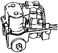
How to Check the Gas Valve CoilsA gas dryer blows air through a burner assembly to heat the air. The burner assembly consists essentially of a gas valve, ignitor and a flame sensor. If any part of the burner assembly malfunctions, the result will be low or no heat and slow drying of the clothes. Caution: Please read our safety information before attempting any testing, maintenance or repairs.
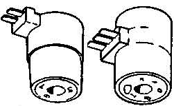
On the gas valve are one or two coils (solenoids) used to open and close the valve to control the flow of gas. If a coil fails, gas will not flow and the dryer will have no heat.
The easiest way to diagnose a problem in the burner assembly is to observe the burner operation. Remove the small access panel at the bottom, front of the dryer, select a high temperature setting and start the appliance. Watch the burner assembly, shortly after starting the dryer the ignitor should begin to glow. Next you should hear the click of the gas valve coil and a flame should ignite. The flame should be mostly blue and it should remain on for a minute or more. If the ignitor glows for several seconds (up to 15 seconds) and then goes out, the problem is probably the coils (solenoids). If the ignitor glows and stays on, then the problem is usually the flame sensor. If it ignites and then quickly goes out, it is most likely a problem with inadequate air flow.
Test the coil for resistance using a multitester. Set the multitester to the ohms setting X10. Place a probe on each terminal. The multitester should change from a reading of infinity to roughly 1300 ohms (+/- 150 ohms) when the probes touch the terminals. If the reading is infinity or substantially different from 1300 ohms, the solenoid should be replaced. |
 |
|


